Designing Automated Chess Board: Motion using discrete coils- Part II
Well, the above video is the result of the last few weeks of rapid prototyping, analysis and iterations. This has been one of the most satisfying streak of engineering I've undertaken in the recent past, with a mix of DIY/Maker approach and also meticulous measurements, analysis, optimizations and automation. The journey took me through characterizing the magnetic field of the coil, correlating it with theoretical equations and making web calculators, making the coils, automating the coil manufacturing and designing and implementing various embedded algorithms for magnetic motion.
Although there are a lot of engineering challenges ahead, these experiments did certainly move the project closer to completion.
The Approach
The final product is intended to be made on a PCB with integrated coil, drivers and embedded logic. Before committing to PCB based coils, I wanted to do a discrete level prototyping to understand what challenges lay ahead. There were multiple parameters to be understood about electromagnetism. What I was interested in here was an analogue of force between an electromagnet and a permanent magnet. Which parameters affects this force and how to optimize them?
Per Biot-Savart law, the electromagnetic field would be affected by current, number of turns, wire thickness, inner diameter, outer diameter, height of the coil and distance at which measurement is being made. Next, often these parameters would be inversely related to each other or would have an unintentional outcome like heat or would have law of diminishing returns. Understanding this would point me in direction of optimal parameters to tune.
Test Bench
The only way to validate a theory is by data collection, probing and measurements. So, I started by listing down the measurements that would be needed for the project and then selecting instrumentation for the same.
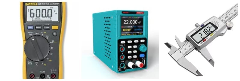
First, the basics, the instruments needed by almost all electromechanical projects. A multimeter, power supply and a caliper.
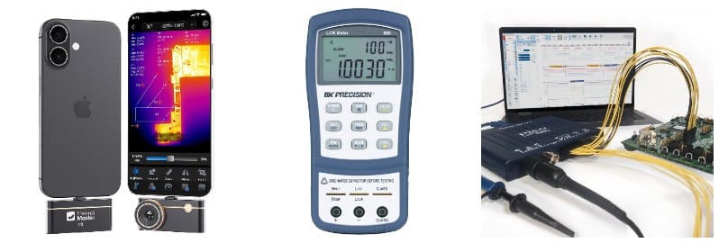
Then few things slightly more advanced, these are the tools which a serious project might utilize at some point in time. An oscilloscope and a current probe, a thermal camera, an LCR meter.
Picoscope and current probe to observe the voltage and current waveforms. This would help analyze protection circuit needed
A thermal camera to see heating of the coils and drivers and evaluate various cooling mechanisms in the future.
The LCR meter was used to validate coil manufacturing and also to corelate coil electrical properties like current, rise time, total current, fall time etc. as function of inductance, resistance of the coil, frequency, duty cycle and voltage of applied input.
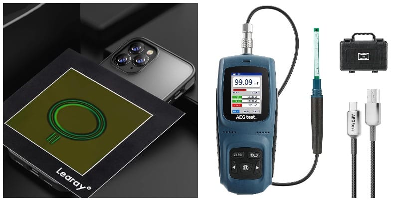
Finally something exotic, unlikely to be used by any project which doesn't use magnetism.
The magnetic field viewing film has been super helpful for understanding the field patterns throughout the data collection stage.
To put numbers on the measurements and calculations and correlating it with theoretical calculations, I got a Tesla Meter.
Theoretical Calculations
Well, we can go into the derivation, but it's unlikely most of the readers would be interested in that. If you're one of the few interested, you can contact me and I can send you the link to the derivation.
In short though, consider the coil to be a series of circle. The radius of each circle is Ri where i is the layer count. The distance of the circle from measurement point is Zj where j is the turn count.
The support has inner diameter Di, height h. Also the wire has thickness t. There is no space between the layers or turns.
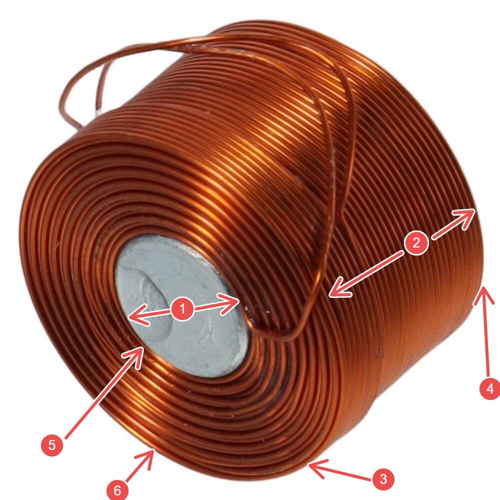
1 - Inner Diameter (Di)
2 - Height of coil
3 - 1st Turn
4 - nth turn
5 - 1st layer
6 - lth layer
Then the magnetic field strength contribution by that loop is given by
\[B = \frac{\mu_0 \cdot I \cdot R_i^2}{2 \cdot (R_i^2 + Z_j^2 )^\frac{3}{2}}\]
Now, there are few inferences I can make out of this.
\(B \propto I\)
\(B \propto \frac{1}{R}\)
\(B \propto \frac{1}{z^3}\)
If we approximate spiral as multiple circles, magnetic field will be sum of all rings.
\[B = \sum_{i=0}^n \sum_{j=0}^l \frac{\mu_0 \cdot I \cdot R_i^2}{2 \cdot (R_i^2 + Z_j^2 )^\frac{3}{2}}\]
\[l = \frac{h}{t}\]
\[R_i = \frac{D+t}{2} + i \cdot t\]
\[Z_j = Z_0 + \frac{t}{2} + j \cdot t\]
BUT, not all circles are made equal.
The top turns are much more closer to the measurement point and thus contribute exponentially more to the final result. The inner layer has smaller radius and thus contribute more to the measurement. Intuitively, adding more turns or layers should atleast mean we are adding more to the field although in smaller amount with expanding layers or further away turns but it comes at a cost and trade off.
Increasing the number of turns or layers also needs more length of wire thus increasing wire resistance and needing more voltage to force same current and increasing power required. Furthermore, the size of the coil (external diameter and height) also increases.
So, deducing what geometry of coil to use also depends on whether we are operating in constant current mode, constant power mode or constant voltage mode. If we operate at constant voltage mode, lower number of turns is beneficial as it increases current drastically and removes lower contributing coil passing higher current through a single coil. At constant current mode, more number of turns will contribute more. Practically, there would be a limit to max voltage we can apply, max current we can supply and max heat we can sink. If we operate at constant power or bring these constraints in, there would be an optimal point below which adding coils is still better but above which adding coils decreases the performance.
So, the next task would be design of experiments and simulations to understand these better. Then collect data and prove or disprove the hypothesis and see if it matches theoretical understanding of the system.
Design of Experiments
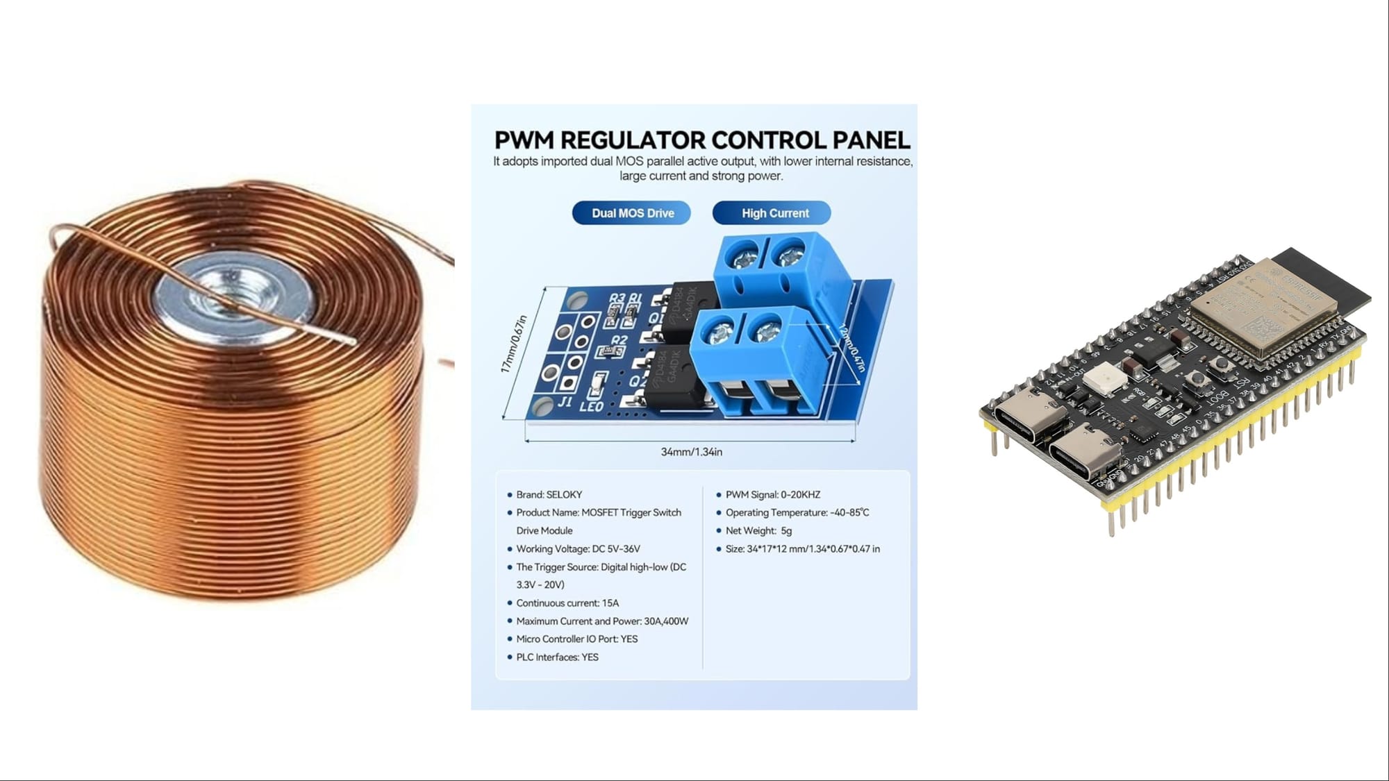
Now that instrumentation was taken care of, I started by designing the set of experiments. To quickly initiate things, I started with buying few off the shelf coils, few MOSFET drivers and an ESP32-S3 board (later replaced by RPi2040) and breakouts for proof of concept. This got me started on the first path of understanding electromagnetism.
Now as per the formula in theoretical calculation, I was interested in studying various effect on magnetic field by varying parameters like current, voltage, power, number of layers, number of turns, inner diameter, height of coil etc. Then, I want to see undesired effects like heat, sound these parameters might have. Finally, come up with algorithms to make various motions.
Experiment 1: Current vs Magnetic Field
Experiment 2: Coil Geometry vs Magnetic Field (simulation)
Experiment 3: PWM vs Magnetic Field
Experiment 4: Linear Motion
Experiment 5: Self made coils
Experiment 5a: Automating Coil Assembly: The side quest
Experiment 6: Coil Grid
Experiment 7: Centering Algorithm
Experiment 8: Linear Motion
Experiments
Experiment 1: Current vs Magnetic Field
In a single coil, keeping all other parameters like geometry and measurement distance constant, vary the current and note down the magnetic field strength.
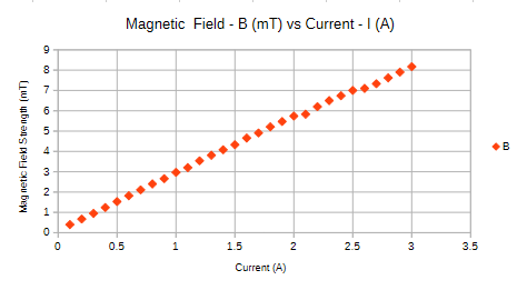
Result, the magnetic field is directly proportional to current as expected
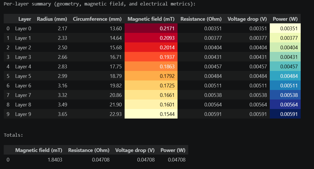
Experiment 2: Coil Geometry vs Magnetic Field (simulation)
Next, if I was going to design my own coils, I needed to understand how does increasing number of turns, layers affect my magnetic field performance. I started by creating a Jupyter notebook for my calculations. Here I can play with number of turns, layers, wire thickness etc. and see what helps and what doesn't.
Keeping
Inner Diameter (Di) = 4mm
Wire Diameter (t) = 0.33mm
Measurement Distance (z) = 1mm
Number of turns per layer (n) = 1
Number of layers (l) = 10
Current (I) = 1 Amp
We get
Outer Diameter (Do) = 10.6mm
Total wire length: 182.68 mm = 0.18 m
DC Resistance: 0.047 Ω
Voltage drop at 1 A: 0.047 V
Power dissipation: 0.047 W
Keeping other things same, just changing the number of turns to 10 and changing number of layers to 1
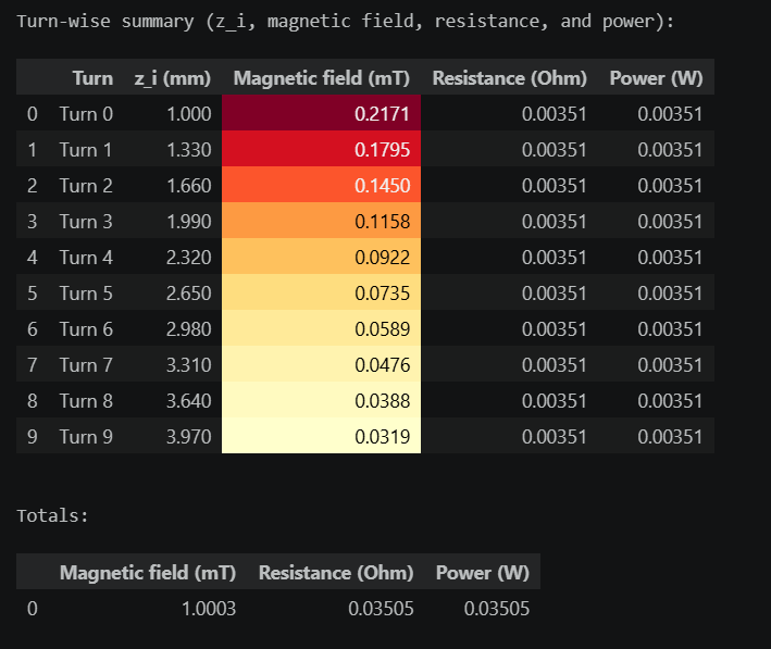
So, at constant current, increasing the number of layers is more beneficial than increasing the number of turns per layer since increasing the number of turns takes the coils further away from measurement point and it's contribution decays exponentially while by increasing the radius, the contribution decreases linearly.
After adding the practical limits of voltage and current and then operating the coil at constant power, the magnetic field strength will have a optimum number of turns and layers post which the strength reduces since the added turns consumes power and decreases current without adding sufficient contribution to magnetic field.
Experiment 3: PWM vs Magnetic Field
Next, I need to be able to control the current through each coil programmatically. I assumed (wrongly) that this should be simple. I can put a MOSFET in between the coil and microcontroller and control the current through coil via PWM by changing the duty cycle of the input.
On collecting the data, I was able to control the frequency and duty cycle through coil, keeping the voltage constant, the current seems to increase with duty cycle with a slight twist. The relationship was not linear.
So I decided to get the big guns out. Took LCR measurements and captured the current waveforms through the coil with some explained and some unexplained behavior.
The current seems to be function of voltage, frequency, duty cycle and circuit elements like freewheeling diode, capacitor etc. The waveform can be split into 4 parts, the rising edge (till it becomes static), the stable part, the falling edge and the off curve.
100Hz, 30% Duty, 5V, 3Amp, no freewheeling diode
1KHz, 30%, 5V, 3Amp, no freewheeling diode
I've yet been unable to put a equation controlling the both as well and decided to park this problem for later. This is a parked problem for now and if anyone wants to collaborate and help me put this relationship together, I'd be very much interested in any help I can get.
But even if I'm not able to put a theoretical equation together and although not linear, I can collect data and put together a curve which works for me by trial and error. So, this should not be a show stopped.
Experiment 4: Linear Motion
Next, I took some of these coils and created a 3D printed fixture to hold them in place. Putting a magnet on the track, turning the coils on and off, I was trying to move the magnet on the track. After few attempts, it did succeed but with few tweaks and learnings.
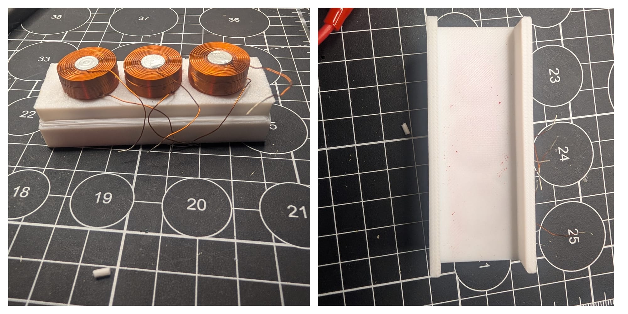
The major learning were
- The magnet diameter has to be bigger and coil geometry needs to support it such that a magnet covers atleast 1 full and 1 partial coil at the same time.
- Having a ferrite material closer by, the attraction between magnet and the ferrite is more than strength of attraction between electromagnet slightly ( few mm) further away and the motion would stop.
Experiment 5: Self made coils
After above learning, it became important for me to create my own coils. This would help me optimize the geometry for my application. Thus I got copper wire and 3D printed a spool to start winding my own coil. Although tedious, the data collection here would help the project further. This would also give me ability to control the geometry and iterate quickly if things don't work out
Experiment 5a: Automating Coil Assembly: The side quest
After winding a few coils myself, I needed something more consistent. I started looking for quick machines I can buy. There were few options but all of those needed hollow core which I didn't want. So, while looking for more options, I gazed over my old 3D printer which has all the components I need. So, I decided to embark on a side quest and build my own coil winding machine.
I took the extruder motor and built a fixture around it. This would be the motor which pulls wire for me onto the spool. Then I synced X motion with extruder turns so that when the wire is being pulled, the head moves horizontally providing clean and evenly spaced coil. Built a fixture to dispense the wire. And iterated over few fixtures, solving problems like pointing accuracy needed (using dispensing needles from syringe), wire tension (using multiple pulley turns) and hacking the gcode to allow cold extrude, long extrude and syncing the exact turns needed. I was able to get something which works consistently.
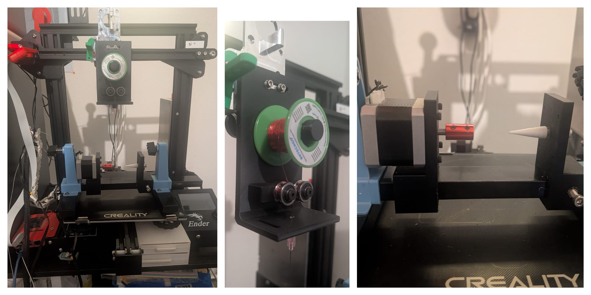
Now, I had a machine to which I can say, here, this is my 3D printed spool, make a coil with 28AWG wire, 30 turns per layer and 12 layers and it'd do the same for me almost consistently.
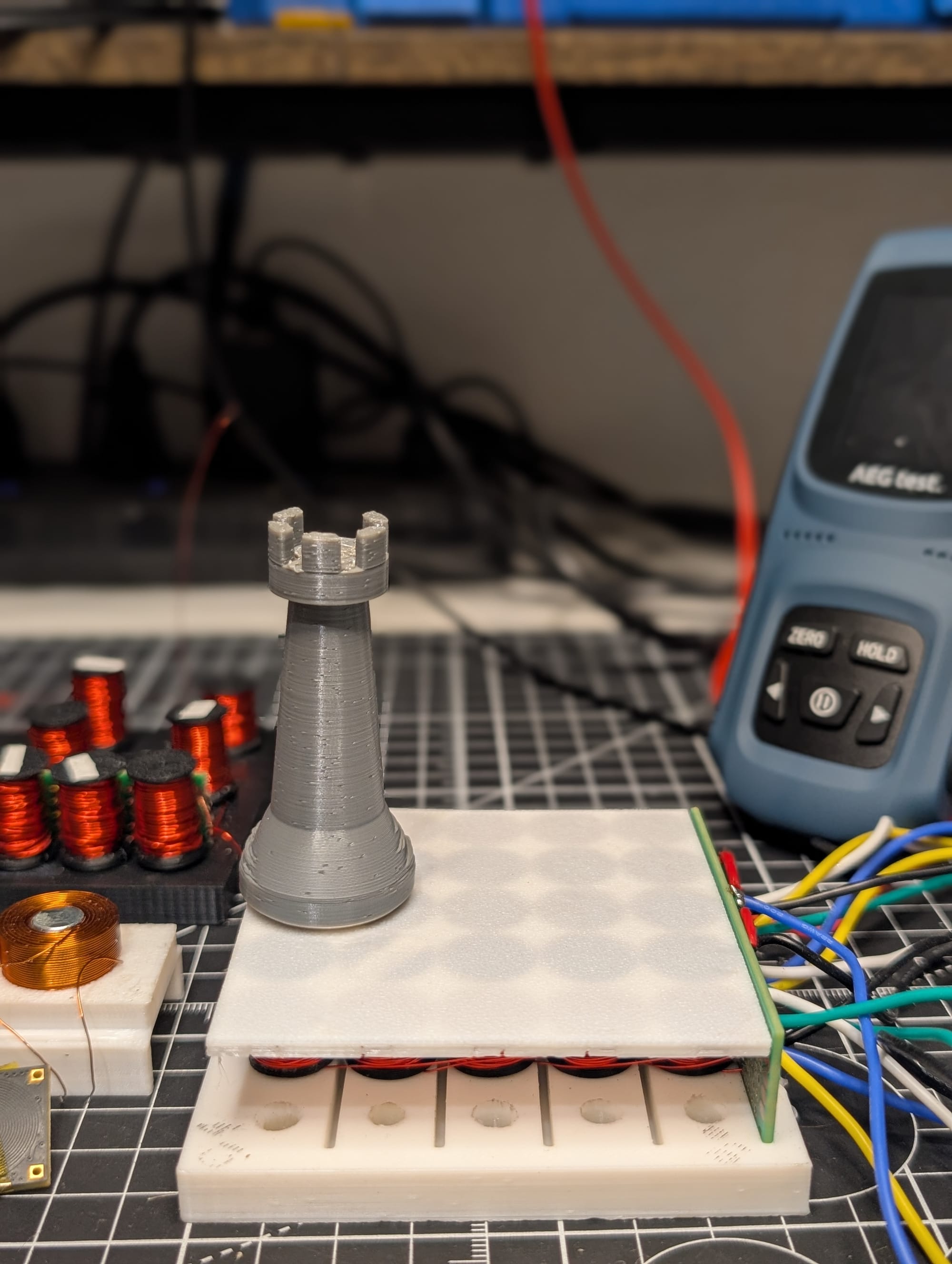
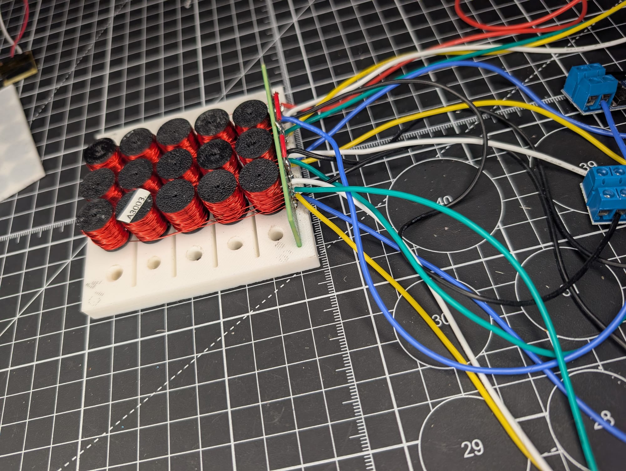
Experiment 6: Coil Grid
Finally, I had enough coils (after weeks of iteration) to put in a 3D printed grid. Organizing the wiring, soldering together the wires and connecting it to the controller. Finally I had the setup to start playing with.
Experiment 7: Centering Algorithm
Placing the magnet manually anywhere on the grid, I wanted to pull center it on a coil.
Just turning the center coil on didn't have enough pull to bring the magnet to it and center it.
Next, making a 3x3 grid on had enough pull (almost) to being the magnet in though it would not center the magnet. Making the center magnet strongest and surrounding ones weaker worked better. Then it was a matter of finding the correct strengths for them. Although, there was one issue, the magnet would still move around if forces slightly. The strength of the permanent magnet is not centered strongly.
Turning on the 2x2 coils had a better result and constrained the magnet better.
Experiment 8: Linear Motion
Finally, the motion. Increasing the current through coil in direction of motion and simultaneously decreasing the previous coil results in the motion. Although, initially there was a audible noise which could be heard. The frequency which I was operating in (the frequency range of ESP32-S3) overlaps audible frequency. In order to get rid of this noise, I needed to operate above the audible frequency range. Well, ESP32-S3 doesn't support that frequency range. So, I had to migrate the microcontroller to something that does (and also which hopefully exists in my grab bag). This turned out to be RPi 2040. Also, the MOSFET needs to support faster switching, although my current of the shelf kit doesn't specify it, they were able to turn on at the higher frequencies. When I migrate to a custom driver board, I'll need to select one which has faster response time, atleast 30KHz i.e. above the audible frequency range.
Next Steps
This was a long stretch of data collection and analysis. There are still unanswered questions and puzzles to be solved. I'll be working on those in the comings weeks and hopefully, given that there are no major roadblocks, I'm targeting to have a working prototype by September.
Few of the next things to work on are
- Collect data with PCB based coils. I bought some from microbot.io to experiment with
- Design a PCB for coils and drivers. Move these to a PCB and experiment with coil geometries. Check if the field is sufficient for motion.
- Piece detection i.e. when user manually moves a piece, identify which piece is kept on which square.
- Board and piece geometry. How big do I want the board and pieces?
- Heat sinking i.e. keeping the product at manageable temperatures
- Power management
- Knight's motion
- Chess engine and software
- Cost optimization
Interested in collaboration, discussion or feedback? I'd be happy to strike a conversation. Ping me on Linkedin or send me an email.